

In the world of metal fabrication, several key machines play a vital role in shaping and cutting metal with precision and efficiency. This ultimate guide provides comprehensive knowledge and insights into the essential products of the industry: Press Brake, Press Brake Tools, Shearing Machine, Laser Cutting Machine, and Power Press. Whether you are a beginner or an experienced professional, this guide will equip you with the necessary information to understand, select, and optimize the use of these machines for your metalworking needs.
Press Brake:
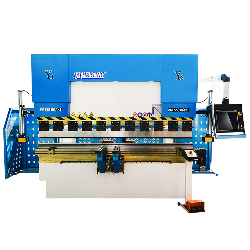
A press brake is a key equipment used in the field of metal fabrication for bending and folding metal sheets. It utilizes pressure to bend the metal sheet into the desired shape. It is commonly used to create bent parts, enclosures, tubing, and other metal components.
A press brake consists of an upper die and a lower die, with the upper die fixed to the frame and the lower die movable through a hydraulic system or mechanical drive system. The metal sheet is placed between the two dies and then bent into the desired angle and shape by applying pressure.
Press brakes typically have the following features and capabilities:
(1)Bending capacity: Press brakes can achieve bends at different angles and radii to meet various workpiece requirements.
(2)Precision: High precision bending results can be achieved by adjusting the position of the upper and lower dies.
(3)Automation: Some modern press brakes are equipped with CNC systems, allowing for automated operation and programming.
(4)Versatility: Press brakes can be used for various bending tasks and different types of metal materials by changing different tools and dies.
(5)Safety: Press brakes are typically equipped with safety devices such as light curtains, protective covers, and emergency stop buttons to ensure operator safety.
Press brakes are widely used in industries such as automotive manufacturing, aerospace, construction, electronics, and more. They are essential equipment for achieving precise and efficient metal fabrication.
There are several types of press brakes commonly used in metal fabrication:
Mechanical Press Brake: Uses a mechanical flywheel and clutch system for bending.
Hydraulic Press Brake: Utilizes hydraulic cylinders for precise bending control.
Servo-Electric Press Brake: Uses electric servo motors for high precision bending.
Pneumatic Press Brake: Relies on compressed air for lighter applications.
CNC Press Brake: Equipped with computerized controls for automated and precise bending operations.
The choice of press brake depends on factors such as material type, thickness, bending requirements, and production volume.
3.Components and Working Principles
A press brake consists of several key components that work together to perform the bending operation. Here are the main components and their functions:
Frame: The frame provides structural support and stability to the press brake.
Bed: The bed is a flat surface where the material to be bent is placed.
Ram: The ram is the moving part of the press brake that applies force to the material for bending.
Die: The die is a tool that shapes the material by providing a specific bending angle.
Punch: The punch is another tool that presses against the material, working in conjunction with the die to bend it.
Backgauge : The backgauge is an adjustable device that positions the material accurately for consistent bending.
4.Key Features and Benefits
Material Placement: The operator places the metal sheet or plate on the bed of the press brake.
Tool Setup: The appropriate die and punch are selected and installed on the press brake.
Backgauge Adjustment: The backgauge is adjusted to position the material correctly for the desired bend.
Bending Process: The ram moves downward, applying force to the material, which is sandwiched between the punch and the die. This bending action creates the desired angle in the material.
Material Removal: Once the bending is complete, the operator removes the bent material from the press brake.
5.Applications and Industries
Press brakes are widely used in various industries for different applications, including:
Metal Fabrication: Press brakes are commonly used in metal fabrication shops to bend and shape metal sheets and plates for various products such as enclosures, brackets, frames, and panels.
Automotive Industry: Press brakes are used in the automotive industry for manufacturing components like chassis, brackets, and body panels.
Aerospace Industry: Press brakes are utilized in the aerospace industry for bending and forming metal parts used in aircraft structures and components.
Construction and Architecture: Press brakes are used in the construction and architectural sectors for bending metal components used in building structures, facades, and decorative elements.
Electronics and Appliances: Press brakes are employed in the manufacturing of electronic enclosures, appliance components, and consumer products.
1.Importance of Press Brake Tools
Press brake tools play a crucial role in the performance and efficiency of press brake machines. Here are some key points highlighting the importance of press brake tools:
(1) Precision Bending: Press brake tools are designed to provide precise and accurate bending angles. They ensure consistent results and help meet the required specifications for the final product. The quality and precision of the tools directly impact the overall quality of the bent parts.
(2) Versatility: Press brake tools come in various shapes, sizes, and configurations to accommodate different bending requirements. They can be customized or interchanged to achieve different bending angles, radii, or complex shapes. This versatility allows manufacturers to produce a wide range of products using the same machine.
(3) Durability and Longevity: Press brake tools are made from high-quality materials such as hardened steel or special alloys, which make them highly durable and resistant to wear and tear. Proper maintenance and regular tool inspections ensure their longevity, reducing the need for frequent replacements.
(4) Efficiency and Productivity: Well-designed press brake tools optimize the bending process, reducing setup time, and increasing productivity. They enable faster bending cycles, allowing manufacturers to produce more parts in less time. Efficient tooling also minimizes material waste and improves overall production efficiency.
(5) Cost Savings: Using the right press brake tools can lead to cost savings in multiple ways. Accurate bending reduces material waste, saving on raw material costs. Efficient tooling reduces setup time and increases machine productivity, maximizing the output per hour. Additionally, durable tools have a longer lifespan, reducing the frequency of replacements and maintenance costs.
(6) Safety: Press brake tools are designed with safety features in mind. They provide proper clamping and holding mechanisms to secure the material during bending, minimizing the risk of accidents. Additionally, using high-quality tools reduces the chances of tool failure or breakage, ensuring operator safety.
(7) In summary, press brake tools are vital for achieving precise and accurate bending results, improving productivity, reducing costs, and ensuring operator safety. Selecting the right tools and maintaining them properly is essential for the efficient operation of press brake machines.
2.Types of Press Brake Tools (including ARC Press Brake Tools)
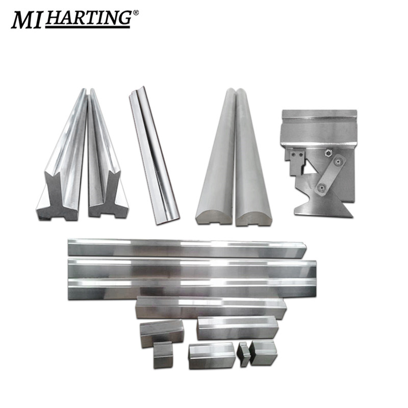
There are several types of press brake tools available, each designed for specific bending applications. Here are some common types of press brake tools:
V-Die: V-dies are the most commonly used press brake tools. They consist of a bottom die with a V-shaped groove and a punch with a matching V-shaped tip. V-dies are versatile and can be used for a wide range of bending angles and materials.
(1) Bottoming Die: Bottoming dies, also known as flat dies, have a flat surface instead of a V-shaped groove. They are used for achieving sharp bends or bending thicker materials where a tighter radius is required.
(2) Gooseneck Punch: Gooseneck punches have a curved shape that allows for deep and offset bends. They are commonly used for bending channels, boxes, and other complex shapes.
(3) Hemming Tool: Hemming tools are used for creating hems or flanges on the edge of a sheet metal part. They consist of a punch and die set that folds the material over itself to create a secure edge.
(4) Radius Tool: Radius tools, also known as radius punches or radius dies, are used for creating curved bends with a specific radius. They are available in various sizes to accommodate different bending requirements.
(5) Multi-V Die: Multi-V dies have multiple V-shaped grooves of different sizes on a single die. They allow for quick and easy tool changes without the need for separate dies for different bending angles.
(6) ARC Press Brake Tools: ARC press brake tools are specialized tools used for bending sheet metal into arc shapes. They are designed to create precise and consistent curved bends, commonly used in applications such as cylindrical parts, tubes, or curved profiles.
ARC press brake tools typically consist of a bottom die with a curved groove and a punch with a matching curved tip. They enable the accurate and repeatable bending of sheet metal into various arc shapes.
3.Material Selection and Coatings
When it comes to press brake tools, material selection and coatings play an important role in their performance and longevity. Here's a brief overview of material selection and coatings for press brake tools:
Material Selection:
(1) Tool Steel: Tool steel, such as D2 or A2, is commonly used for press brake tools due to its high hardness, wear resistance, and toughness.
(2) Carbide: Carbide inserts or tips are used for heavy-duty applications or when bending abrasive materials. Carbide provides excellent wear resistance but is more brittle than tool steel.
(3) High-Speed Steel (HSS): HSS is another option for press brake tools. It offers good toughness and wear resistance, but not as high as tool steel.
Coatings:
(4) Nitride Coating: Nitride coatings, such as TiN (Titanium Nitride) or TiCN (Titanium Carbonitride), improve the surface hardness and wear resistance of the tool. They are suitable for general-purpose bending applications.
(5) DLC Coating: DLC (Diamond-Like Carbon) coatings provide excellent hardness, low friction, and high wear resistance. They are ideal for bending stainless steel and other difficult-to-form materials.
(6) PVD Coating: Physical Vapor Deposition (PVD) coatings, like TiAlN (Titanium Aluminum Nitride), enhance the tool's performance by reducing friction and increasing wear resistance.
(7) Chrome Plating: Chrome plating is a common coating for press brake tools. It provides good corrosion resistance and reduces friction during bending operations.
The selection of material and coating depends on factors such as the type of material being bent, the bending application, and the desired tool life. It's important to choose the right combination of material and coating to ensure optimal performance and durability of the press brake tools.
4.Tooling Configurations and Considerations
When it comes to press brake tools, the tooling configurations and considerations are crucial for achieving accurate and efficient bending operations. Here are some important aspects to consider:
Tooling Configurations:
(1) V-Die: The V-die is the female tool that provides the desired bend shape. It comes in various widths and angles to accommodate different material thicknesses and bending requirements.
(2) Punch: The punch is the male tool that contacts the material and applies force to create the bend. It also comes in different shapes and sizes to achieve specific bend angles and radii.
(3) Multi-V Die: Multi-V dies have multiple V-shaped grooves of different widths and angles. They allow for bending different material thicknesses and angles without changing the die.
(4) Gooseneck Punch: Gooseneck punches have a curved shape that allows for deep or offset bends where space is limited.
(5) Hemming Tools: Hemming tools are used for creating hemmed edges or flanges on sheet metal.
Considerations:
(1) Material Thickness: The tooling configuration should be selected based on the material thickness being bent. Thicker materials may require larger tooling to accommodate the increased force and prevent tool damage.
(2) Material Type: Different materials have varying properties, such as hardness and ductility, which can affect the tooling selection. Harder materials may require tougher tooling materials or coatings.
(3) Bend Angle and Radius: The desired bend angle and radius dictate the selection of punch and die configurations. Sharp bends require smaller punch radii, while larger radii are needed for gentler bends.
(4) Tooling Alignment: Proper alignment between the punch and die is essential for achieving accurate and consistent bends. Misalignment can result in uneven bends or tool damage.
(5) Tooling Maintenance: Regular inspection and maintenance of the tooling are necessary to ensure optimal performance and longevity. This includes cleaning, lubrication, and replacement of worn-out components.
By considering the tooling configurations and these important factors, you can select the appropriate press brake tools for your specific bending requirements. This will help you achieve precise and efficient bending operations while prolonging the tooling life.
5.Tool Maintenance and Longevity
(1) Regular cleaning: Clean the press brake tools regularly to remove debris, dirt, and metal shavings. Use appropriate cleaning agents and tools to avoid damaging the tool surfaces. Ensure that the tools are completely dry before storing them.
(2) Lubrication: Apply lubrication to the press brake tools as recommended by the manufacturer. Lubrication helps reduce friction and wear, improving the tool's lifespan. Follow the manufacturer's guidelines for the type and frequency of lubrication.
(3) Inspection and repair: Regularly inspect the press brake tools for signs of wear, damage, or deformation. Check for any cracks, chips, or excessive wear on the cutting edges. If any issues are detected, promptly repair or replace the damaged parts to prevent further damage and ensure accurate bending results.
(4) Proper storage: Store the press brake tools in a clean and dry environment to prevent corrosion and damage. Use dedicated tool racks or boxes to keep the tools organized and protected. Avoid placing heavy objects on top of the tools to prevent deformation.
(5) Operator training: Proper training of operators is essential for tool maintenance and longevity. Educate operators on the correct usage techniques, operating limits, and safety precautions. Encourage operators to report any issues or abnormalities with the tools promptly.
By following these maintenance tips, you can extend the lifespan of your press brake tools and ensure consistent and accurate bending operations. Regular maintenance not only improves tool performance but also contributes to the overall safety and efficiency of the bending process.
6.Advanced Tooling Technologies and Innovations
Advanced tooling technologies and innovations have significantly improved the performance and capabilities of press brake tools. Here are some key advancements in press brake tooling:
(1) High-strength materials: Press brake tooling is now made from high-strength materials such as hardened steel alloys or carbide. These materials offer superior durability, wear resistance, and longer tool life compared to traditional tooling materials.
(2) Coatings and surface treatments: Advanced coatings and surface treatments, such as TiN (Titanium Nitride) or DLC (Diamond-Like Carbon), are applied to press brake tools to enhance their performance. These coatings reduce friction, improve wear resistance, and prevent material adhesion, resulting in improved bending quality and longer tool life.
(3) Precision tooling systems: Modern press brake tooling systems feature precision-ground tooling with tight tolerances. These systems ensure accurate and repeatable bending results, reducing setup times and increasing productivity.
(4) Quick-change tooling systems: Quick-change tooling systems allow for rapid tooling setup and changeovers. These systems utilize standardized tooling holders and clamping mechanisms, enabling operators to switch between different tooling setups quickly and efficiently.
(5) 3D modeling and simulation: Advanced software tools enable 3D modeling and simulation of bending processes. These tools help optimize tooling designs, simulate bending sequences, and detect potential collision or interference issues before actual production. This reduces setup time, minimizes errors, and improves overall efficiency.
(6) Custom tooling solutions: Tooling manufacturers now offer custom tooling solutions tailored to specific bending applications. These solutions include specialized tool profiles, custom tool coatings, and even tooling with integrated sensors for process monitoring and control.
These advancements in press brake tooling technologies have significantly improved productivity, accuracy, and tool life. By adopting these innovations, manufacturers can achieve higher efficiency, reduce downtime, and produce high-quality bent parts consistently.
1.Understanding Shearing Machines
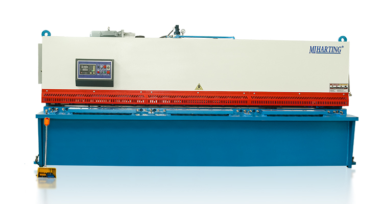
Shearing machines are industrial mechanical devices used for cutting metal sheets and other materials. They apply shearing force to cut the materials into desired shapes and sizes. Shearing machines are widely used in manufacturing and metalworking industries to produce various products and components.
The working principle of shearing machines involves placing the material on a shear table and applying force through cutting blades to cause the material to fracture. Shearing machines can perform operations such as straight cutting, curved cutting, and angle cutting. Depending on the specific requirements, shearing machines can have different cutting capacities and precision.
There are various types of shearing machines, including hydraulic shearing machines, mechanical shearing machines, and manual shearing machines. Hydraulic shearing machines use hydraulic systems to provide cutting force and offer high power and precision, making them suitable for large-scale and heavy-duty cutting tasks. Mechanical shearing machines use mechanical mechanisms to provide cutting force and are typically more compact and cost-effective, suitable for medium-sized cutting tasks. Manual shearing machines require manual operation and are suitable for small-scale and simple cutting work.
The cutting capacity of shearing machines depends on their maximum cutting thickness and cutting width. Larger shearing machines generally have higher cutting capacity and can handle thicker and wider materials. The cutting precision of shearing machines is influenced by factors such as blade sharpness, adjustment of blade clearance, rigidity of the frame, and material characteristics.
Safety considerations are important when operating shearing machines. Operators should receive proper training on the operation procedures and safety precautions of shearing machines. Additionally, appropriate personal protective equipment, such as safety goggles and gloves, should be worn. Regular inspection and maintenance of shearing machines are necessary to ensure their proper functioning and safe operation. Following the operation manual and manufacturer's recommendations is crucial to ensure the safety and effectiveness of operating shearing machines.
In summary, shearing machines are essential cutting tools widely used in manufacturing and metalworking industries. Understanding the principles, types, cutting capacity, and safety precautions of shearing machines can help in selecting the appropriate machine and operating it safely and efficiently.
2.Hydraulic vs. Mechanical Shearing Machines
Hydraulic and mechanical shearing machines are two common types of shearing machines used in industrial applications. Here's a comparison between the two:
Power Source:
(1) Hydraulic Shearing Machines: These machines use a hydraulic system to generate the cutting force. The force is applied through hydraulic cylinders powered by a hydraulic pump. Hydraulic shearing machines offer high power and can handle heavy-duty cutting operations.
(2) Mechanical Shearing Machines: These machines use mechanical mechanisms, such as gears, levers, and flywheels, to generate the cutting force. The force is applied directly through the mechanical components. Mechanical shearing machines are generally more compact and cost-effective.
Power and Precision:
(1) Hydraulic Shearing Machines: Due to the hydraulic system, hydraulic shearing machines can provide high cutting power. They are capable of cutting thick and hard materials with precision. The hydraulic system allows for better control and adjustment of the cutting force, resulting in accurate and consistent cuts.
(2) Mechanical Shearing Machines: Mechanical shearing machines provide a lower cutting power compared to hydraulic ones. They are suitable for medium-duty cutting tasks. However, the cutting precision of mechanical shearing machines can be affected by factors such as mechanical wear and tear, which may require more frequent adjustments and maintenance.
Size and Space:
(3) Hydraulic Shearing Machines: Hydraulic shearing machines are generally larger and require more space due to the hydraulic system components, such as the hydraulic pump, cylinders, and hoses.
(4) Mechanical Shearing Machines: Mechanical shearing machines are more compact and take up less space. They are often preferred in smaller workshops or where space is limited.
Cost:
(1) Hydraulic Shearing Machines: Hydraulic shearing machines are typically more expensive due to the complexity and cost of the hydraulic system components.
(2) Mechanical Shearing Machines: Mechanical shearing machines are generally more affordable and cost-effective.
In summary, hydraulic shearing machines provide high power and precision, making them suitable for heavy-duty cutting operations. They are larger and more expensive. On the other hand, mechanical shearing machines are more compact, cost-effective, and suitable for medium-duty cutting tasks. The choice between hydraulic and mechanical shearing machines depends on the specific cutting requirements, available space, and budget considerations.
3.Components and Operation
Components of a Shearing Machine:
(1) Shear Table: This is the flat surface or bed on which the material to be cut is placed. It provides support and stability during the cutting process.
(2) Cutting Blades: These are the sharp blades that perform the actual cutting of the material. They are typically made of high-quality tool steel and are securely mounted on the machine. The blades can be straight, curved, or angled, depending on the desired cutting operation.
(3) Blade Clearance Adjustment: Shearing machines often have a mechanism for adjusting the clearance between the upper and lower blades. This adjustment allows for precise control of the cutting gap, ensuring clean and accurate cuts.
(4) Back Gauge: The back gauge is a movable stop or fence located behind the shear table. It helps in positioning the material accurately for repetitive cutting operations. The back gauge can be manually adjusted or controlled by a motorized system.
(5) Drive System: The drive system provides the power to move the cutting blades. In hydraulic shearing machines, the drive system consists of a hydraulic pump, cylinders, and valves. In mechanical shearing machines, it typically involves mechanical components such as gears, levers, and flywheels.
(6) Control Panel: The control panel houses the controls and switches for operating the shearing machine. It allows the operator to start and stop the machine, adjust settings, and monitor the cutting process.
Operation of a Shearing Machine:
(1) Material Preparation: The material to be cut is prepared by ensuring it is clean, straight, and properly aligned with the shear table. Any protective coatings or films on the material should be removed.
(2) Material Placement: The material is placed on the shear table, ensuring it is aligned with the back gauge if applicable. The operator should take care to position the material securely and avoid any obstructions that could interfere with the cutting process.
(3) Blade Clearance Adjustment: The blade clearance is set according to the thickness and type of material being cut. This adjustment ensures proper shearing without damaging the material or the blades. The manufacturer's guidelines or machine manual should be followed for the correct blade clearance settings.
(4) Cutting Operation: Once the material is properly positioned and the blade clearance is set, the operator initiates the cutting operation. In hydraulic shearing machines, the hydraulic pump is activated to provide the necessary cutting force. In mechanical shearing machines, the operator engages the drive system, which transfers power to the cutting blades.
(5) Monitoring and Control: During the cutting process, the operator monitors the operation to ensure smooth and accurate cutting. The control panel may provide indicators or displays for monitoring the cutting speed, blade position, and other parameters. Any abnormalities or issues should be addressed promptly.
(6) Material Removal and Repeat: After the cutting operation is complete, the cut pieces are removed from the shear table. The process can be repeated for subsequent cuts, adjusting the back gauge if necessary.
It's important to note that the specific operation of a shearing machine may vary depending on the machine model and manufacturer. Operators should always refer to the machine's manual and receive proper training before operating the shearing machine.
4.Cutting Capacity and Accuracy
Cutting Capacity and Accuracy are important considerations when using a shearing machine. Let's discuss each of them:
Cutting Capacity:
(1) Shearing machines have a specified cutting capacity, which refers to the maximum thickness and width of the material that can be effectively cut. The cutting capacity is determined by factors such as the power of the machine, the strength of the blades, and the rigidity of the shear table.
(2) It is crucial to choose a shearing machine with a cutting capacity that matches the requirements of the materials you will be working with. Attempting to cut materials beyond the machine's capacity can result in poor cutting quality, blade damage, or even machine malfunction.
Cutting Accuracy:
(1) Cutting accuracy refers to the ability of the shearing machine to make precise and consistent cuts. It is influenced by several factors, including the design and condition of the machine, the sharpness and alignment of the blades, and the control and monitoring systems.
(2) To achieve high cutting accuracy, it is important to maintain the shearing machine properly. Regular blade sharpening and replacement, as well as routine maintenance and calibration, can help ensure accurate cuts.
(3) The operator's skill and experience also play a significant role in achieving cutting accuracy. Proper material positioning, adjustment of blade clearance, and careful monitoring of the cutting process are essential for obtaining precise and clean cuts.
Factors Affecting Accuracy:
(1) Blade Condition: Dull or damaged blades can lead to uneven cuts and reduced accuracy. Regular inspection and maintenance of the blades are necessary to maintain cutting precision.
(2) Blade Clearance: Incorrect blade clearance can result in distorted or incomplete cuts. It is important to set the appropriate blade clearance for the material being cut.
(3) Material Alignment: Proper alignment of the material with the shear table and back gauge is crucial for accurate cuts. Misalignment can cause crooked or uneven cuts.
(4) Machine Rigidity: The rigidity of the shearing machine, including the shear table and frame, affects cutting accuracy. A sturdy and well-maintained machine provides better stability and reduces the chances of deflection during the cutting process.
It is recommended to follow the manufacturer's guidelines and recommendations for the specific shearing machine being used. Regular maintenance, blade inspection, and operator training are essential to ensure optimal cutting capacity and accuracy.
5.Safety Considerations
Safety considerations are of utmost importance when operating a shearing machine. Here are some key safety measures to keep in mind:
(1) Read and Follow the Manual: Familiarize yourself with the manufacturer's instructions and safety guidelines provided in the machine's manual. Understand the machine's features, controls, and potential hazards before operating it.
(2) Personal Protective Equipment (PPE): Always wear appropriate PPE, including safety glasses or goggles, gloves, and ear protection. Depending on the specific machine and the materials being cut, additional protective gear such as a face shield or apron may be required.
(3) Machine Inspection: Before starting the machine, inspect it for any signs of damage, loose parts, or malfunctioning components. Ensure that all safety guards and devices are in place and functioning correctly.
(4) Training and Competence: Only trained and authorized personnel should operate a shearing machine. Proper training should cover machine operation, safety procedures, emergency shutdown, and handling of materials.
(5) Material Handling: Use caution when handling materials, especially large or heavy ones. Use lifting equipment or assistance when necessary to avoid strain or injuries.
(6) Emergency Stop: Familiarize yourself with the location and operation of the emergency stop button or switch. Be prepared to use it in case of any emergency or unsafe situation.
(7) Blade Safety: Never reach into the cutting area while the machine is in operation or attempt to adjust the blades without proper training. Always wait for the machine to come to a complete stop before making any adjustments or maintenance.
(8) Housekeeping: Maintain a clean and organized work area. Remove any debris, scraps, or obstructions that may interfere with the machine's operation or cause accidents.
(9) Lockout/Tagout: Follow proper lockout/tagout procedures when performing maintenance or repairs on the machine. This involves disconnecting the power source and ensuring that it cannot be re-energized accidentally.
(10) Regular Maintenance: Adhere to the recommended maintenance schedule for the shearing machine. This includes blade sharpening, lubrication, and inspection of mechanical and electrical components.
Remember, safety should always be the top priority when operating any machinery. If you have any concerns or encounter any issues with the shearing machine, stop the operation immediately and seek assistance from a qualified technician or supervisor.
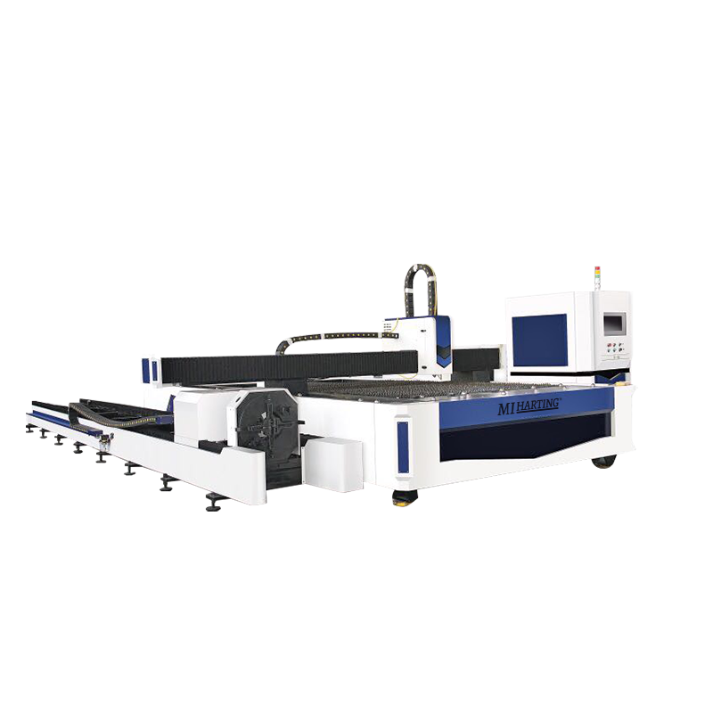
Laser Cutting Machine:
1.Introduction to Laser Cutting:
Laser cutting is a highly precise and versatile method of cutting various materials using a high-powered laser beam. It has revolutionized the manufacturing industry by providing a faster, more accurate, and more efficient alternative to traditional cutting methods. Laser cutting machines are used in a wide range of industries, including automotive, aerospace, electronics, signage, and jewelry making.
Laser cutting works by directing a laser beam onto the material to be cut. The laser beam is generated by a laser resonator, which consists of a laser medium (such as CO2, fiber, or neodymium-doped crystals) and a system for exciting the laser medium (such as electrical discharge or diode pumping). The laser beam is then focused onto the material using a series of mirrors and lenses, which increases the intensity of the beam. The intense heat of the laser beam melts, burns, or vaporizes the material, creating a clean and precise cut.
2.Types of Laser Cutting Machines:
There are different types of laser cutting machines available, each with its own advantages and suitable applications. The most common types include CO2 lasers, fiber lasers, and neodymium lasers.
CO2 lasers are the most widely used type of laser cutting machine. They use a mixture of carbon dioxide, nitrogen, and helium as the laser medium. CO2 lasers are versatile and can cut a wide range of materials, including non-metallic materials such as plastics, wood, and fabrics, as well as metals.
Fiber lasers use optical fibers as the laser medium. They are highly efficient and are primarily used for cutting metals, including stainless steel, aluminum, and copper. Fiber lasers offer high beam quality, which results in faster cutting speeds and improved precision.
Neodymium lasers use neodymium-doped crystals (such as neodymium-doped yttrium aluminum garnet or Nd: YAG) as the laser medium. They are known for their high energy and are used for precision cutting and engraving. Neodymium lasers are commonly used in applications that require high power and fine detail, such as jewelry making and micro-machining.
3.Advantages and Limitations:
Laser cutting offers several advantages over traditional cutting methods. One of the key advantages is its high precision and accuracy. Laser cutting machines can achieve intricate and complex cuts with minimal distortion. They also provide excellent edge quality, eliminating the need for additional finishing processes.
Another advantage is the speed and efficiency of laser cutting. Laser cutting machines can cut at high speeds, resulting in faster production times and increased productivity. They can also cut multiple parts simultaneously, further improving efficiency.
Laser cutting is a non-contact cutting method, which means there is no physical contact between the cutting tool and the material. This reduces the risk of damage to the material and allows for cutting delicate or fragile materials.
However, laser cutting does have some limitations. The thickness capacity of a laser cutting machine depends on the power of the laser and the type of material being cut. Thicker materials may require multiple passes or a more powerful laser to achieve a clean cut. Additionally, laser cutting machines can be expensive to purchase and maintain, making them more suitable for high-volume production environments.
4.Material Compatibility and Thickness:
Laser cutting machines can cut a wide range of materials, including metals, plastics, wood, textiles, and more. The compatibility of a material with laser cutting depends on its ability to absorb the laser energy. Materials that are highly reflective, such as copper or aluminum, may require higher laser power for cutting.
The thickness of the material that can be cut depends on the power of the laser and the type of material. Laser cutting machines can typically cut thin materials with high precision. For example, a CO2 laser cutting machine can cut up to 25mm thick steel, while a fiber laser cutting machine can cut up to 30mm thick steel. However, the maximum thickness capacity may vary depending on the specific machine and laser power.
It is important to consider the material compatibility and thickness capacity of a laser cutting machine before selecting the appropriate machine for a specific application. Consulting with a laser cutting machine supplier or manufacturer can help determine the best machine for a particular material and thickness requirement.
Power Press:
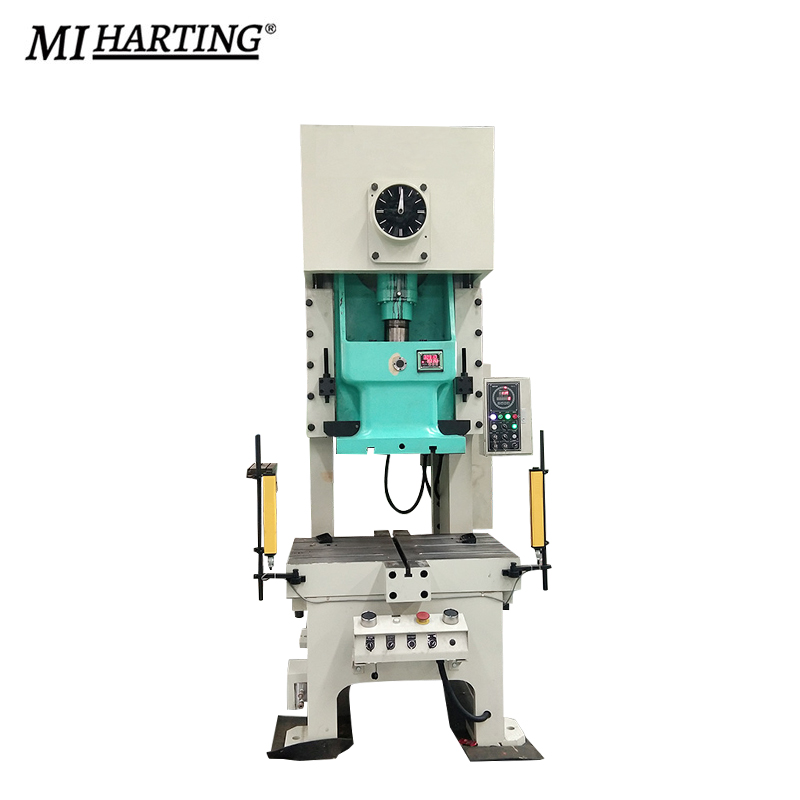
1.Exploring Power Press Machines:
Power press machines, also known as press machines or stamping presses, are versatile machines used in metalworking for various operations such as punching, bending, forming, and blanking. They are commonly used in industries such as automotive, manufacturing, construction, and appliance production. Power press machines come in different sizes and configurations to accommodate different applications and production requirements.
Power press machines are designed to apply force to a workpiece using mechanical or hydraulic systems. They are capable of exerting high pressure to shape, cut, or form metal sheets or other materials. Power press machines can be categorized into mechanical and hydraulic types based on their power source and operation.
2.Mechanical vs. Hydraulic Power Press:
Mechanical power presses use mechanical force, typically generated by a flywheel and a crankshaft, to perform operations. They are known for their high speed and productivity. Mechanical power press machines have a mechanical clutch or brake system that controls the stroke and stopping motion of the ram. They are suitable for high-volume production environments where speed and precision are important.
Hydraulic power presses, on the other hand, use hydraulic systems to generate force. They utilize hydraulic cylinders to apply pressure to the ram and perform operations. Hydraulic power press machines offer more control and flexibility in terms of force adjustment and speed modulation. They are often used for operations that require precise force control or for applications that involve deep drawing or forming of materials.
The choice between a mechanical or hydraulic power press depends on the specific requirements of the application. Factors such as the type of operation, material thickness, production volume, and precision requirements should be considered when selecting the appropriate power press machine.
3.Components and Operation:
Power press machines consist of several key components that work together to perform various operations. These components include the frame, slide or ram, bolster, die, clutch or brake system, and control system.
The frame provides the structure and support for the machine. It is usually made of cast iron or steel to withstand the forces exerted during operation. The slide, also known as the ram, moves up and down to apply force to the material. It is guided by the frame and can be driven by a crankshaft or hydraulic cylinders.
The bolster is a flat surface on which the material is placed. It provides support to the workpiece during the operation. The die is a specially shaped tool that performs the desired operation, such as punching a hole or bending a metal sheet. The die is mounted on the bolster or the ram, depending on the type of operation.
The clutch or brake system controls the stroke and stopping motion of the ram. In mechanical power press machines, a mechanical clutch or brake is used to engage or disengage the flywheel, controlling the motion of the ram. In hydraulic power press machines, the hydraulic system controls the movement of the ram.
The control system of a power press machine can vary depending on the specific machine and its features. It can range from simple manual controls to advanced computer numerical control (CNC) systems. CNC systems offer precise control over the machine's operation, allowing for programmable and repeatable processes.
4.Punching, Bending, and Forming Capabilities:
Power press machines are capable of performing various operations, depending on the tooling and dies used. Some common operations include punching, bending, forming, blanking, coining, embossing, and deep drawing.
Punching is a process of creating holes or shapes in a material using a punch and die set. Bending is the process of deforming a material to form angles or curves. Forming involves shaping a material to create three-dimensional objects or complex geometries. Blanking is the process of cutting out a flat shape from a larger piece of material. Coining is a process that involves compressing a material to create a precise shape or pattern. Embossing is the process of creating raised or depressed
Conclusion:
By delving into the comprehensive knowledge provided in this ultimate guide, you have gained a solid understanding of Press Brake, Press Brake Tools, Shearing Machine, Laser Cutting Machine, and Power Press. Armed with this knowledge, you can confidently select, operate, and optimize these machines to achieve precise and efficient metal fabrication results. Remember to prioritize safety, regular maintenance, and stay updated with the latest advancements in the industry to stay ahead in the ever-evolving world of metalworking.